- Other Fluke companies:
- Fluke
- Fluke Biomedical
- Fluke Networks
- Fluke Process Instruments
Improving Accuracy of Power and Power Quality Measurements
Dave Coombes Fluke Precision Measurement
Abstract - To calibrate power and power quality measurement instruments such as flicker meters or harmonic measurement devices, several alternative techniques are generally used or proposed:
- Using a reference device to make measurements which can be compared against those made by the UUT.
- Applying variable loads to a static, impedance loaded power line to induce required conditions.
- Generating the required signals with a precision signal source.
This paper discusses the third option. There are a number of benefits to this approach, as well as a number of difficulties to overcome and decisions to be made to implement it effectively.
Introduction
Accurate measurement of electrical power is becoming more important, as electrical power becomes a more essential and valuable commodity. It is also becoming more crucial to measure more attributes of electrical power as deregulation, and distributed generation systems result in huge increases in the number of transactions taking place where electricity is bought and sold. Buyers obviously are keen to ensure they are getting what they paid for, and distributors are keen to ensure that power supplied does not adversely affect the integrity of their network. NIST have stated that “additional low-uncertainty measurements are needed to ensure the accurate sale of power”. and “More precise measurements of standard billing parameters will be needed (e.g. energy, demand) to support contract management”[1].
At the same time, many driving forces are in place to make this measurement more difficult, and error prone. Power is becoming dirtier and more distorted, and measurements beyond straight power and energy (such as flicker) become commonplace
The impacts of this are obviously many. Two perhaps are of concern to us in the metrology community. Firstly, how do we maintain integrity, and improve uncertainties on measurements being made that are well understood i.e. power and energy, but where measurement conditions are now quite substantially different from those in the past. Secondly, how do we ensure adequate uncertainty measurements are made on some of the newer measurements being called for today, such as flicker.
Existing methods
Reference Measurement Devices
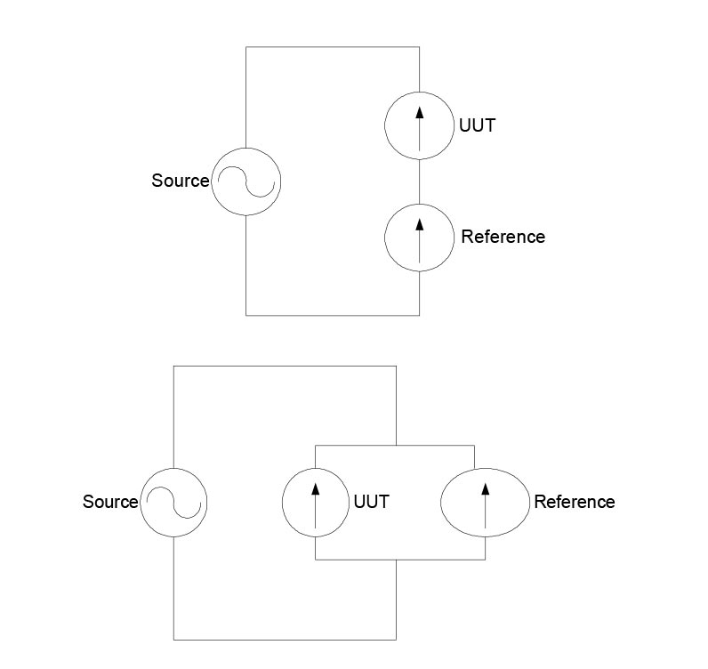
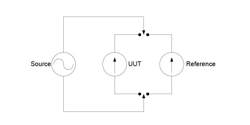
The use of reference measurement devices is a well understood technique in today’s metrology. The same measurement is made with the UUT and with a reference instrument whose uncertainties are well defined. A comparison made between the two measurements yield the errors in the UUT. Depending on the nature of the instruments and measurements involved, the two measurements may be made at the same time using some kind of series and/or parallel connection, or sequentially by switching or substitution. (fig 1) In the measurement of power, this technique is employed widely, particularly with power meters and revenue meters (kilowatt hour meters)
Problems with this approach
This approach relies on the fact that errors and uncertainties in the source are effectively cancelled out by using the same source for measurements made with the UUT, and with the reference. In the case of power measurement, the source is generally the mains power line, or is derived from the mains power line with some conditioning applied. However, this technique can only be considered valid under the following conditions
(a) The mains power line is clean and undistorted (i.e. noise and interference free, and perfectly sinusoidal).
(b) The UUT will be deployed in making measurements under the same conditions when calibration is complete.
(c) The UUT and reference present identical loads to the supply.
If (a) is not true, and the supply is imperfect, different response mechanisms to effects such as harmonic distortion may result in different results between the UUT and the reference. Depending on time of day, harmonic distortion on the power line varies as overall loads change which further compounds potential for errors.
If (b) is not true, then the UUT will effectively be making a different measurement to the one for which it has been calibrated. Consider the situation where a kilowatt hour meter is calibrated at a meter shop where the supply used may be close to perfect as in (1) above, but is then deployed in the field where harmonic distortion is likely to be relatively high and extend to high numbers of harmonics. Differences of up to 68% in measured power were observed by Dr. P.S. Filipski and P.W. Labaj of the NRC during an evaluation of four different reactive power meters in the presence of high harmonic distortion. [2].
If (c) is not true, different currents will flow in the UUT and reference, in the case of the parallel connection or substitution method, and a different potential will be developed across the UUT and reference in the case of the series connection. In either case there will be measurement error
Switched or variable loads
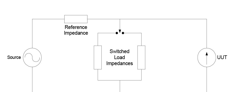
This technique is used particularly with flicker meters. Here, a load is switched to develop a potential difference across a reference impedance in order to simulate the modulation on mains power supplies classified as flicker (Figure 2). Careful selection of the reference impedance and the switched impedances yield signals of sufficient accuracy to calibrate flickermeters.
Problems with this approach
Again, this approach depends on a number of preconditions
(d) The mains power line is perfectly clean and undistorted (i.e noise and interference free, and perfectly sinusoidal).
(e) The source impedance is effectively zero.
If (d) is not true, supply borne signal artifacts may prevent accurate measurements being made. There are two primary mechanisms identified which can affect this measurement. Presence of an inter-harmonic on the supply will cause a beat with the supply fundamental frequency (and any harmonics which may present) and be interpreted and measured by the flicker meter as flicker. Or of course the supply itself may have flicker upon it.
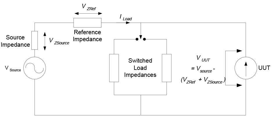
If (e) is not true, and an imperfect signal source is employed, inaccurate levels of modulation will be developed at the input to the flickermeter (Figure 3)
Limitations of both approaches
There is a growing requirement to characterize and verify the performance of power measurement instruments in the presence of differing forms of distortion and anomalies. IEC61000 – 4 – 30 (currently in draft form) and IEEE P1159.1 both require that power quality measurement instruments are calibrated in the presence of simultaneous, multiple forms of anomolous signal. For example, a flicker measurement is calibrated in the presence of controlled amounts of harmonic distortion. While the limitations in accuracy described above may be acceptable in some cases, neither of the approaches outlined above is able to provide the facility for calibration when simultaneous degradations are present.
Calibration through signal sourcing
This paper proposes a solution in the form of a calibration signal source that resolves the issues outlined above. The system is fundamentally a signal source which provides high accuracy phantom power (separate voltage and current) to calibrate power measurement devices. In addition to pure sinusoidal signals, the system can also provide the capability to supply all currently defined forms of mains power supply degradations (frequency variation, harmonic distortion. interharmonics, fluctuating harmonics, flicker and dips and swells). The system proposed can be realized through the use of arbitrary waveform generators and accurate amplifiers under the control of a digital feedback loop. (Figure 4).
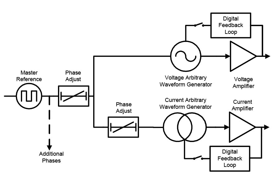
Problems encountered with Modulated signals
The use of a digital feedback loop provides a mechanism for maintaining accuracy on complex signals, in particular on signals where specified amounts of harmonic distortion are added. This technique allows for correction of further distortions introduced by the processes of digital to analogue conversion and amplification. Uncertainties for power of 200ppm are achievable, on sinusoidal and non-sinusoidal signals.
However, for signals which are amplitude modulated, such as flicker, fluctuating harmonics and inter-harmonics, this techniques does present problems. Quite simply, the feedback loop would attempt to correct the very anomalies which are being introduced. Therefore the digital feedback loop must be automatically disabled when generating these types of signals. This of course serves to reduce the overall system accuracy, which becomes heavily reliant on the accuracy of the amplifiers.
In order to restore a higher level of accuracy, the system may be connected to the load, and a non-modulated signal applied. With the digital feedback loop in operation, system inaccuracies and distortions are corrected. Then when a modulated signal is selected, the feedback loop is disconnected, but correction factors stay active. Due to good amplifier design, overall system accuracy can thus be maintained for a period long enough to perform a number of measurements.
Various amplifier topologies have been investigated in realizing this design. A transformer-less, dc coupled design was chosen in order to achieve the desired low frequency performance. This low frequency performance itself has the potential to provide difficulties to the user. This is described below.
When the fundamental (nominally the 50 or 60Hz supply frequency) is amplitude modulated, as is the case when generating flicker, sum and difference frequencies are also produced i.e.
If a waveform mCoswmt modulates a ‘carrier’ Coswct, the result is:

Consider the case where the modulating signal is rectangular or square. There will be odd harmonics in the modulating waveform which might cause the ‘difference’ term to be zero or close to it, e.g. with a square wave of 20Hz modulating a carrier of 60Hz there will be a DC term caused by the difference between the third harmonic of the 20Hz modulating square wave and the 60Hz signal. The amplitude of the DC term will be up to 1/3 * m/2.
Whilst this is perfectly correct and may be required for some users, DC components may not be welcome in some equipment. To solve this problem, It is currently proposed to perform real time calculations as a user defines waveforms to identify this possibility. Users will be warned of the possibility of DC or very low frequency components being present if and when the currently defined signal is applied to the UUT.
Advantages of this system
The system as proposed has a number of advantages over other methods.
- Distortion on mains power line, or non-zero source impedance of mains power line, has no impact on overall measurement accuracy.
- Instruments can be calibrated with signals more representative of the signals they will be deployed to measure.
- Calibration uncertainties due to load variations are largely eliminated.
- Multiple anomalies can be applied simultaneously in order to verify an instrument’s interdependency between various signal types, and it’s capability to correctly distinguish and measure each form of distortion.
Conclusion
Existing methods of calibrating power measurement devices have their limitations, although until recently these have largely been somewhat inconsequential. As electricity distribution and transaction systems develop, these limitations will begin to impact the requirement to make more accurate and more complex measurements.
A fresh approach, using a technique of signal sourcing rather than measurement comparison eliminates many of the causes of measurement uncertainty, and provides a simple method for calibrating measurements where few, if any, methods existed previously.
References
[1] NIST Deregulation workshop, February 2000
[2] P. Filipski, P. Labaj, "Evaluation of Reactive Power Meters in the Presence of High Harmonic Distortion", IEEE Transactions on Power Delivery, October 1992
- Home
- Products
- New Products
- Electrical Calibration
- RF Calibration
- Data Acquisition and Test Equipment
- Temperature Calibration
- Humidity Calibration
- Pressure Calibration
- Flow Calibration
- Process Calibration Tools
- Calibration Software
- Service and Support
- All Calibration Instruments
- Handheld Test Tools
- Purchase Info
- News
- Training and Events
- Literature and Education
- Service and Support
- About Us

